6.2.10. Pipes and Ducts
Pipes or ducts can be added to / deleted from the system via the system scheme editor by right-clicking on the icon.

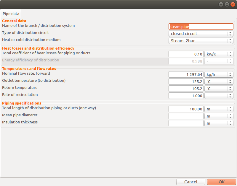
6.2.10.1. General Data
Type of Distribution Circuit
There are three types of pipe/duct available:
closed circuit
Heat supply by a distribution circuit formed by a forward and a return pipe/duct. The rate of recirculation in this case may be less than 1. Heat losses for both forward and return pipes/ducts are considered.
open circuit
Heat supply by a single pipe/duct from supply equipment to process. No recirculation. Heat losses are considered only for one pipe/duct.
built-in heater/cooler
Special case for a direct coupling of equipment to the process (e.g. built-in heaters and coolers) A virtual distribution pipe is added to the model with zero thermal losses and a distribution efficiency of 1.
6.2.10.2. Heat Losses and Distribution Efficiency
Heat Loss Coefficient: the heat loss coefficient for the whole piping/duct system (forward and return)
Distribution Efficiency: defined as the ratio of heat delivered to the process (UPH_proc) and the heat fed into the pipe (USH_pipe)
6.2.10.3. Temperatures and Flow Rates
Nominal temperatures and flow rates
6.2.10.4. Piping Specifications (optional)
These data are used for estimating the piping/duct heat loss coefficient if this is not explicitly given.
Default values assumed are:
- for the case that pipe diameters and insultatino thickness is given:
effective heat transfer coefficient of the insulation material (including correction for thermal bridges): k = 0.05 W/mK
pipe heat loss coefficient per unit length of piping: UA_l = 2 pi k / ln(d_o / d_i)
- otherwise
UA_l = 0.0005 kW/mK
The total heat loss coefficient is then UA = 2 UA_l * l for a closed circuit and UA = UA_l * l for an open circuit, with l being the (one-way) length of piping.